Installing a Catch Basin

A catch basin is the piece of a drainage system that catches water running across pavement or turf before it becomes a problem, then hands it off to a pipe that carries it away. Most drainage failures on parking lots, driveways, and commercial sites are not pipe failures. They are inlet failures: a basin that sits at the wrong elevation, a grate too small for the flow, or a sump that filled up because nobody ever cleaned it.
Installing a basin is not complicated work, but there is no slack in the details. Rim elevation, invert elevation, bedding, and backfill compaction each have a tolerance, and missing any one of them produces a structure that ponds water instead of collecting it.
This guide walks through a typical precast catch basin installation on a small commercial or residential-drainage project, from sizing the inlet through backfill and cleanup.
What a Catch Basin Actually Does
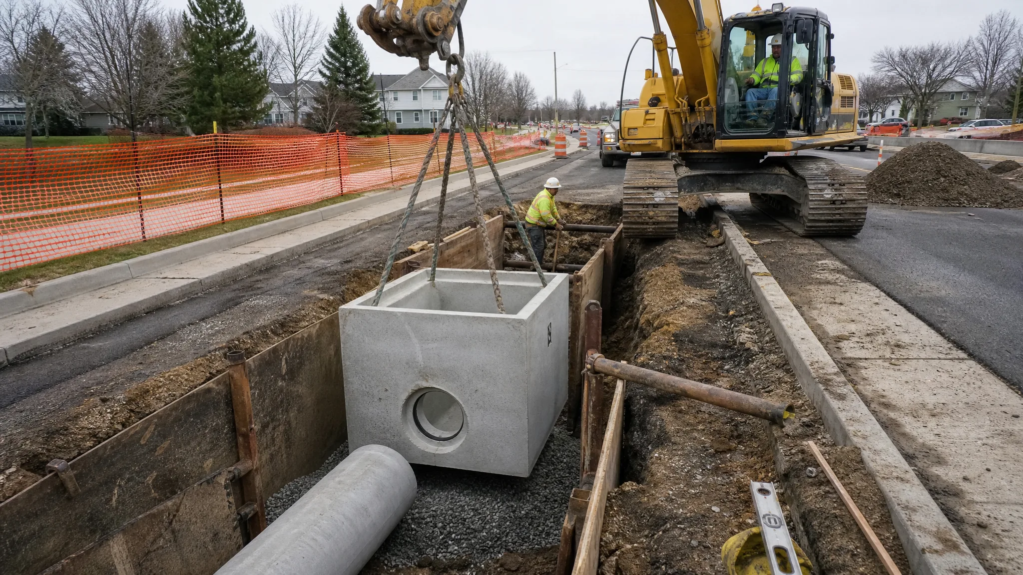
A catch basin is a box set into the ground with an open grate at the surface and one or more outlet pipes leaving the side or bottom. Water enters through the grate, drops into the basin, and leaves through the outlet. Anything heavier than water, such as sand, grit, and small debris, settles in the sump below the outlet instead of traveling downstream.
Different from a manhole, which provides access for maintenance on a pipe line, and different from a yard drain, which handles small local collection, a catch basin combines inlet, settlement, and connection in one structure. Common configurations include round basins for yards and driveways, square basins for higher flows and easier debris access, and inline basins placed within trench drain runs. Materials run from HDPE and polypropylene for residential sizes up to precast and cast-in-place concrete for municipal and roadway work, and available sizes span roughly six inches to forty-eight inches and larger.
Where the inlet is, and how big it is, determine what the basin can accomplish. Placement decisions belong with the grading plan, and the drainage principles in creating effective drainage systems during excavation apply whether you are building a small yard system or a sitewide storm layout.
Size the Inlet Before You Dig
Sizing comes down to one question: can the grate, the basin, and the outlet pipe pass the peak flow from the area draining to them? Work through it in order.
- Measure the contributing drainage area. That means everything that slopes toward the basin, in square feet or acres.
- Assign a runoff coefficient to each surface. Published values run roughly 0.80 to 0.95 for pavement and roofs and 0.10 to 0.35 for lawns, depending on slope and soil.
- Find the design rainfall intensity for your location and storm return period.
- Compute peak flow with the Rational Method, Q = CiA.
- Choose a basin and grate with inlet capacity above that flow, and an outlet pipe that carries it away. One cubic foot per second is about 449 gallons per minute, which is a useful conversion when comparing a computed flow to a manufacturer's capacity rating.
If one basin cannot cover the area, the answer is usually several smaller basins rather than one oversized structure. The grate is nearly always the bottleneck, and grating capacity does not scale the way basin volume does.
Pipe capacity belongs to the outlet side of the problem. A storm line that cannot carry the flow makes an accurate inlet useless, and minimum pipe slopes are set by municipal standard. Many jurisdictions specify a minimum storm pipe slope of 0.5%, and designers target enough slope to keep a self-cleansing velocity so the line does not fill with sediment.
Sump Depth: Sediment Storage, Not Drainage
The sump is the dead storage below the lowest outlet where grit settles instead of washing downstream. Residential plastic basins typically give six to twelve inches of sump depending on which knockout you pipe from. Municipal precast details commonly call for a twenty-four inch minimum.
More sump does not drain water any faster. It buys time between cleanings. Every inch you raise the outlet relative to the bottom of the basin adds sediment storage below the outlet, which is why the outlet configuration and the sump depth are really one decision.
Set the outlet invert at or below every inlet pipe so connected lines never trap standing water, size the outlet to handle the basin's design flow, and seal unused knockouts. A basin with a low outlet and a shallow sump will pass water fine and clog twice as often.
Grates, Load Ratings, and ADA
Match the grate to what will cross it and what will fall into it. Four styles cover most situations.
- Flat grates sit flush and take sheet flow from every direction. This is the default for driveways, patios, parking areas, and lawns, and it comes in load classes from pedestrian-rated plastic to ductile iron for roadway service.
- Dome or atrium grates stand proud of grade and keep accepting water after leaves or mulch cover the base. They do not belong under wheels or in walking paths.
- Curb-opening inlets use a vertical throat cast into the curb face and take gutter flow with no grate to clog. These are typically precast concrete structures on municipal streets.
- Combination inlets pair a grate with a curb opening behind it, so the curb opening keeps working when leaves blind the grate mid-storm. This is the standard choice where ponding is unacceptable.
Load class is a safety decision, not a preference. Pick the class for the heaviest wheel that will ever cross the grate, whether that is a lawn mower, a delivery truck, or a loaded dump truck. Municipal standard details commonly call for precast sections with frame and cover designed for AASHTO H-20 loading unless a higher load is specified.
Where a grate sits in an accessible route, openings are regulated. The 2010 ADA Standards limit openings in floor and ground surfaces so they do not allow passage of a sphere more than one-half inch in diameter, and elongated openings must be placed so the long dimension is perpendicular to the direction of travel. Pedestrian-rated grates exist for exactly this reason, and they should be specified wherever foot traffic crosses the inlet.
Setting Rim and Invert Elevations
Two elevations control whether a catch basin works: where the grate sits relative to grade, and where the pipes sit relative to each other.
For rim elevation, the convention is simple. In turf, set the grate about one inch below the surrounding grade so water actually flows to it. In pavement, set it flush at the true low point, with the surrounding surface feeding it from the intended directions. A basin set too high collects nothing; set too low in asphalt it becomes a pothole.
For the pipe work, slope outlet piping toward discharge at one to two percent, which is one-eighth to one-quarter inch per foot, and remember that municipal storm systems often have a lower minimum of 0.5%. Confirm the actual requirement in the specification you are building to.
Elevations are the most common cause of failure. A basin at the wrong rim or invert elevation, on a system that was otherwise sized correctly, is why water still stands in the parking lot after a storm. Set them from a benchmark rather than a visual read, and verify the grate elevation against the finished grade after paving, not before.
Excavation and Bedding
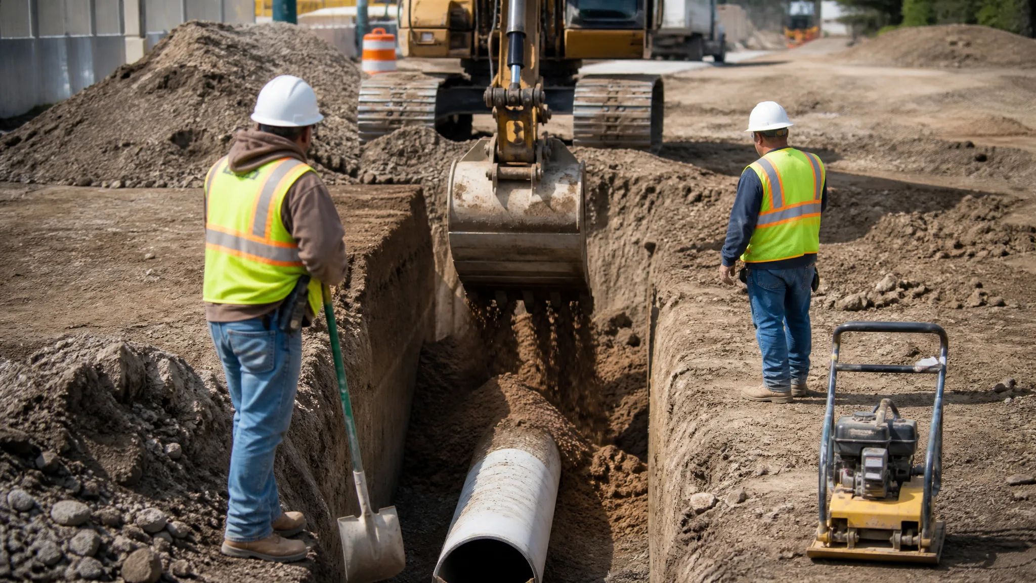
Dig the excavation wide enough to work around the basin and deep enough for the bedding, the structure, and its frame. Where the excavation passes five feet in depth, or where anyone is working in it, the protective system requirements for trenches apply, and it is worth reviewing when trench protection is required before the bucket goes in. In most places the utility locate rule applies to this work as well, so calling 811 comes before excavation, not after.
Bed the basin on a level layer of compacted granular material. The base has to be flat and uniform so the structure is not bearing on a single high point, because a basin that is out of level is out of level for the pipe connections too. If groundwater is present in the excavation, deal with it before setting the structure rather than fighting it during the pour or the set. Dewatering an excavation covers the options.
Pipe bedding follows the same principle. For flexible pipe, standard practice calls for bedding material extending roughly six inches above the pipe crown, placed in lifts and compacted to about 90 to 95 percent relative compaction with hand tampers or walk-behind plate compactors. The pipe has to be supported along its length, not just at the ends.
Setting the Basin and Connecting Pipe
Set the structure with slings or a lifting device rated for the weight, and lower it slowly onto the bedding. Do not drop it and do not pry it into position. Check the rim elevation and level again after the structure is seated, then check the invert elevations of every inlet and outlet before making a single pipe connection.
Making the connections is where small errors compound. Pipe cut too short leaves a gap that will leak and undermine the backfill. Pipe cut with the wrong bevel or the wrong coupling type breaks the joint under load. Confirm the connection detail called out in the specification for your pipe material, and seal every unused opening in the structure.
Once the pipe is in, verify the whole run before backfill: invert elevations, pipe alignment, joint integrity, and grate seating. This is the last easy moment to correct something. After backfill and paving, corrections cost multiples of the original work.
Backfill and Compaction
Backfill around a catch basin in a roadway or pavement section is a structural fill operation, not a matter of pushing dirt back in.
The Federal Highway Administration's drainage guidance for backfill over conduit is a good reference for the principle: fill placed in horizontal layers no more than six inches thick before compaction, with a minimum of 95 percent Standard Proctor maximum density required, and the first layer directly over a conduit left uncompacted to protect it. Local specifications vary on the exact percentage and whether Standard or Modified Proctor is the basis, so read the spec sheet for your project.
Compact in thin lifts on both sides of the structure at the same time. Bringing the fill up evenly on one side while the other stays empty creates unbalanced pressure that can shift the basin. Around the structure, use equipment that reaches the work: a plate compactor or walk-behind roller in tight spots, a larger vibratory roller where the area is open. Choosing the right compaction equipment covers matching the machine to the lift and material.
Where the basin sits in a pavement section, the top of the backfill needs to be dense enough to carry the pavement without settling into a dip at the inlet. That means density testing before paving if the specification calls for it, and reworking the area if the tests fail rather than paving over it and hoping.
Inlet Protection During Construction
A new catch basin is a direct path for sediment to leave the site, because it is designed to collect whatever the surface delivers. During construction, it has to be protected.
Inlet protection typically takes the form of a sediment control device around or over the grate, such as a stone and fabric berm, a filter bag, or a prefabricated insert, along with regular cleaning. Match the method to the site's stormwater plan, and inspect after every significant storm. Any site with a stormwater permit has stormwater plan obligations that cover this. See what a SWPPP is for the permit side and installing a silt fence for the perimeter control that works alongside inlet protection.
Track-out is the other half of keeping sediment out of the system. A stabilized construction entrance at the site exit, covered in temporary construction entrances, keeps the mud from ever reaching the inlet in the first place.
Maintenance, Common Failures, and What to Bid
Catch basins need cleaning. The sump that makes the structure useful is also the part that fills up, and once sediment reaches the outlet invert, the basin starts passing grit downstream. Annual inspection is a common baseline, with cleaning scheduled based on how much material the site actually sheds.
The failures to watch for are predictable. Basins that pond usually sit at the wrong rim elevation or have an outlet invert above an inlet. Basins that flood nearby areas usually have a grate with too little open area or one that is blinded with debris. Basins that sink or crack are usually backfilled without adequate compaction or set on an unlevel base. Basins that smell or back up on the pipe side usually have a blocked or undersized outlet line.
For bidding, the scope is excavation, bedding, structure and grate supply, setting, pipe connections and fittings, backfill and compaction, testing if required, inlet protection during construction, and final grade restoration. Add a line for traffic control and pavement repair when the work touches a roadway, and account for the protection requirements if any part of the excavation goes deep. A clear scope that names the load class of the frame and grate, the sump depth, and the compaction requirement prevents most of the arguments that come up after the water starts running.
Do the sizing, the elevations, and the compaction properly and a catch basin quietly does its job for decades. Skip them and it becomes the reason the site floods.